SJTAG Architectural Concept
Green Paper
By Bradford G. Van Treuren, SJTAG Chair Emeritus
BEGINNINGS
It has been almost ten years since the formation of the IEEE System JTAG study group was formed. In that time there have been many new standards created that have one thing in common – they are rooted in IEEE 1149.1[1]. It has not been a clear journey as many of these standard looked more like a moving target for how they can be used at the board and system level. It wasn’t until the advent of the IEEE 1149.1- 2013 release and the IEEE P1687[2] draft that the concept of decoupling the structure of the Test Data Register (TDR) from the access mechanism that is used to communicate with the TDR became an important cohesive concept. Each of the inheriting standards incorporates the use of a TDR to communicate with the special features they represent.
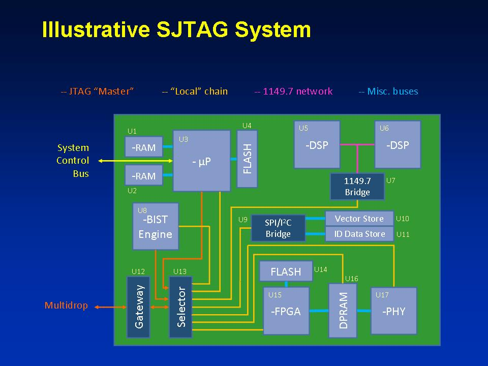 Figure 1 Illustrative SJTAG System
Thus, the common feature for all of these standards is the TDR; contrary to the idea that these are standardized on the JTAG TAP Controller. The TDR is based on the protocol established by the TAP State Machine as defined by the 1149.1 standard. This protocol defines the Capture-Shift-Update timing and scan order of the information in a standardized format equivalent to a data communications protocol physical layer. This serial scan protocol defines how the data gets sent and received inside the chip – the Data Link. As long as the data format and structure adheres to the protocol defined for the TDR, it is not critical to understand where and how that data arrives to the internal structure of the device. With that said, one can abstract out the concept of the access mechanism used to transport the data through the board and system to the TDR. This abstraction allows for the decoupling of the transported data from the access mechanism used to transport that data. The concept of the access mechanism is also known as the Access Link or Access Interface for a device. Defining the Data Link and Access Link is not the only thing required for use at the board and system level of a design. There also needs to exist a controlling infrastructure to manage and coordinate the multitude of device instrumentation found throughout a system as well as the relationship for how these instruments are connected together – the structure of the scan network. To help understand what a System Under Test represents, a theoretical model of a typical system is depicted in Figure 1.
PUTTING IT TOGETHER
From Figure 1, the reader is able to realize the scan network does not consist of a single unified scan chain. In fact, every device supporting 1149.1 consists of multiple scan chains hidden behind a set of instructions providing access to them. So the 1149.1 state machine also provides a level of separation between the data link (Scan DR) and the access link (Scan IR) abstraction. Selector devices and gateway devices (as shown by U12 and U13 on Figure 1) add yet another method for control of a scan chain based on the protocol defined by their designer. For a Scan Path Linker, such as the Lattice Semiconductor BSCAN-2[3] or various Firecron[4] devices, there is a particular instruction that has to be selected and a specific value applied to the associated TDR of the Selector to allow connection to a sub-chain at the next physical hierarchical level or to bypass that connection. Once configured, the Selector is set up with a BYPASS instruction for further access through the device until a new configuration is required. In other words, a specific configuration has to be established in the device to provide the means for passing the data through to the next level of the physical hierarchy. This configuration requires a separate procedure to define the new behavior for the device that must be coordinated with the rest of the board logic. This is similar to an address decoding step used in decoding data packets over a data network. Instead of decoding the route on the fly, as is done with packet based Ethernet, the structure follows more of what older switch based telecom system used to use for voice service. A connection gets established for a specific path, which remains connected until reconfigured.
There are procedures that have to be called to configure the structure of the interface to allow the data to pass to the next level in the physical hierarchy. The key to realize is this configuration does not have to require the use of the 1149.1 protocol to perform the connection. A good example is the Texas Instruments Addressable Scan Port Protocol [5] which repurposes the JTAG pins for a multi-drop backplane for a different control protocol that performs the address and configuration of the device. Others use I2C or SPI commands to accomplish the addressing. The key point to understand is the access to the next level in the physical hierarchy has to occur as a separate operation first before the data can be passed through that interface. This is exactly what we saw with the 1149.1 Scan IR and Scan DR flow; an instruction has to be entered into the instruction register before a TDR can be selected.
ILLUSTRATION
The most common example of the test interactions for embedded instrumentation is found between U15 and U16 of Figure 1. U15 can be used to test U16 directly with the Boundary Scan Register (BSR) – a special TDR – of U15, using the instruction EXTEST. Patterns may be applied to the interface of U16 as multiple scan operations through the BSR. However, some instances of U16 require a faster interface than can be achieved with the scan rate provided by the BSR. For those cases, a special embedded instrument may be loaded into U15 to apply the patterns at a faster rate. The data will be applied via a different TDR and the instrument may produce the patterns itself. So from the same JTAG interface of U15, different scan path architectures exist inside of U15 for testing U16. However, the connection to U15 from the Test Manager will remain the same.
The interactions between U5 and U6 present a different problem. In a previous discussion, a variety of SJTAG Templates were created to describe the different architectures that could be used for testing SERDES links between U5 and U6 (e.g., Single Tx and Rx in U5 with loop back in U6, multiple Tx in U5 paired with multiple Rx in U6). What wasn’t discussed previously was the introduction of U7, a protocol converter between 1149.1 and IEEE 1149.7[6] to handle the transition to a 2-wire JTAG interface to U5 and U6 from a 5-wire JTAG interface on the board. As depicted, U7 needs to be configured to pass the remapped signals to U5 and U6 with the appropriate addressing model. Data targeted to U5 needs to be sent to U5 and ensuring U6 will not respond to commands sent to the U5 instance. Since the testing between U5 and U6 need to be coordinated with each other, the connection to U5 and U6 has to be adjusted depending on what device is the corresponding recipient. This has to be handled and set up before the next burst of data is sent to the TDR of the device’s instrument.
VISUALIZATION
To understand the complexity involved with accessing a specific TDR within a system, one has to understand the diversity of roles the TDR may embody within a design. Then one has to consider that role replicated as multiple instances of that TDR for instrumentation, such as, temperature sensors, voltage monitors, or other important aspects of system control. To complicate the perspective further, one needs to realize that each of these features must exist in concert with many other features embodying the essence of the different standards inheriting from the TDR architecture of 1149.1.
Figure 2 depicts a generalized visualization of a typical SJTAG domain for a System Under Test. At the bottom level is the Access Interfaces defining how the data is transported to each particular device within the system. Above that is the representation of the particular standard implementing the corresponding feature for the TDR as a modular definition based on the corresponding description provided by each of the standards. So for a P1687 Module the representation is defined by the PDL and ICL definitions for the instrument. Each of the other standards have their own descriptions defining the attributes corresponding to the features defined by that specific standard. These descriptions provide the elaboration of the Routines (procedures) and Algorithms required for communicating with the target TDR for a particular feature. The System Model represents the structural topology of the system down to the various instruments enumerated for the design. The SJTAG Test Manager represents the software and tooling necessary to control and coordinate the operations performed by each of the instrumentation specified for the System Under Test.
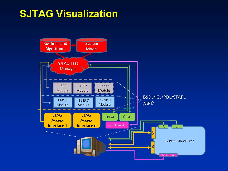 Figure 2 SJTAG Visualization
ECO-SYSTEM FOR DATA TRANSFER
The command and control of instrumentation at the system level requires the observer to realize there is a coordinated embodiment of a special eco-system defining the transport interface and the data provided to the instrument. An example eco-system for an External Memory BIST instrument is shown in Figure 3.
The iNEMI Board Assisted-BIST (BA-BIST)[7] study group has defined a series of templates which describe the interaction of the embedded instrument with the features targeted for testing that exist outside of the device where the instrument resides. Figure 3 also shows the difference in scope between the IEEE 1149.1-2013 standard and the IEEE P1687. P1687 describes the connectivity down to the instrument interface. Whereas, 1149.1-2013 describes the connectivity down to the TDR used to interface with the instrument logic. In this example, the Access Interface or AccessLink is defined by a JTAG TAP Controller with the corresponding JTAG Interface inside the device. The cloud labeled SJTAG Infrastructure represents the aggregation of logic residing at the board and system level, which provides connection from the Test Manager to the instrument in the device. The arrow from the cloud to the device labeled Alt I2C represents an access path that could also be supported, which provides connection to the P1687 scan network inside of the device. This alternate interface would require a special access link controller that maps the I2C commands to scan operations for the P1687 scan network.
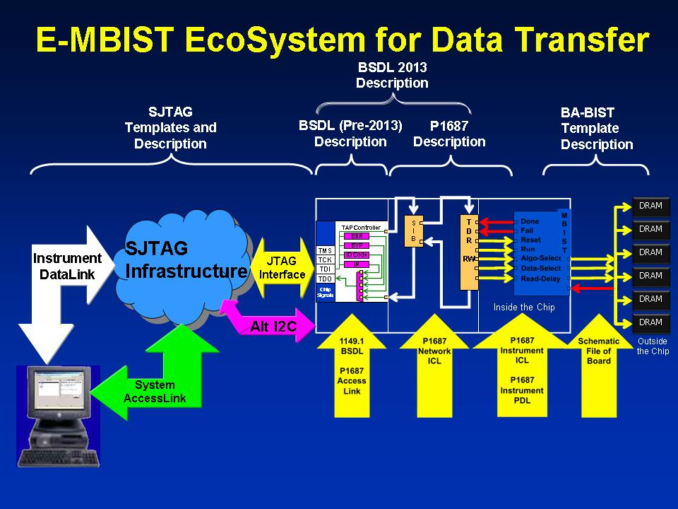 Figure 3 Eco-System for Data Transfer
ACCESS/DATA PATH CONCEPT
Figure 4 highlights the abstraction of the physical hierarchy at the system and board level. There can be N levels of physical hierarchy separating the Test Manager from the TDR being accessed. To communicate with a particular TDR or set of TDR’s, the configuration has to be established first before any data can be transferred to the TDR. Thus, there is a connection procedure that must be performed prior to transferring data to the TDR. That procedure may be a No-Operation procedure if the connection is already established. In the case where the connection does not yet exist, the Test Manager needs to traverse down the physical hierarchy and establish the connection to the path or sub-network used to communicate with the target TDR. This may take several iterative procedure calls to handle the connection at each hierarchical level. Once the Test Manager has established a connection to a particular level, it must determine the procedure that has to be followed to connect to the next lower level. That procedure may involve the use of a completely different access protocol or method than the previous level. It is the role of the Test Manager to understand the descriptions found in the System Model (see Figure 2) and determine what procedures to call in order to establish that connection via the defined AccessLink for that level. Once the connection is established for the DataLink, the data may be transported through that connection or that connection may be used to establish a connection through the next level of the hierarchy. Where the data is not able to be directly presented in the Capture-Shift-Update (C-S-U) format over a DataLink, the DataLink may need to be manipulated in such a way as to emulate that C-S-U behavior with commands in its own protocol or indirectly via intermediary instrumentation. Once all connections have been established to a TDR, the data may be scanned to the TDR using the Capture-Shift-Update protocol defined by 1149.1.
So what is an AccessLink? An AccessLink is a combination of gating logic connecting the DataLink on the left hand side of the SJTAG Cloud with the DataLink on the right hand side of the Cloud. It also consists of a controller that defines the selection algorithm and protocol used by the selection algorithm to establish or prevent the connection between the two DataLink portals.
The DataLink, on the other hand, represents the infrastructure required to transmit the data to the next level of the physical hierarchy. This link represents the signals required to transport messages between the Test Manager and the TDR over the defined interface. The DataLink establishes a communications portal between Cloud entities within the hierarchy of the system. The DataLink may provide an indirect means of manipulating the portal to provide the equivalent communications at the lower level in the hierarchy. This may be by manipulating special registers in the Cloud instrumentation that project the equivalent signal patterns in the other DataLink portal or there may be dedicated instrumentation within the Cloud entity to perform the translation of the protocols automatically.
The Cloud represents the collection of the logic to bridge the left side DataLink with the right side DataLink and the AccessLink controller that manages the overall connection through the Cloud. The Cloud may be as simple as a switch connecting the left hand side DataLink to the right hand side DataLink directly. The Cloud may also act as a translator between two different types of DataLink medium. For example, an 1149.1 interface may be the DataLink on the left hand side of the cloud and an I2C interface may exist as the DataLink on the right hand side of the cloud. An embedded instrument in the Cloud entity would then be controlled to perform the proper manipulation of that instrument’s TDRs to perform the appropriate communications on the right hand side DataLink. The Test Manager must be aware of the protocol defined for each side and rely on the routines (as specified in the Routines and Algorithms database) defined for that DataLink to perform the operation required over that interface. The routines defined for a Cloud must provide a means for transmitting the TDR data correctly to the other side of the Cloud.
The System Model, Routines, and Algorithms describing the System Under Test need to clearly define the addressing, control, and structure of the entire pathway to each of the TDRs needing to be controlled by the Test Manager. Thus, a set of common data can be identified, but there will also need to be data specific to a particular Cloud implementation that describes the subtle dependencies between the left and right side DataLink portals. There is both a structural aspect to the Cloud as well as a behavioral aspect. The Test Manager must rely on the procedures provided by the Cloud designer to support the control of the communications through the Cloud.
Since SJTAG involves serial scan chains that are connected together, there may be many sub-network scan chains concatenated together for multiple devices at a single hierarchical level. These have to be managed in concert. The data scanned through that corresponding level has to account for the additional TDRs represented in that scan network.
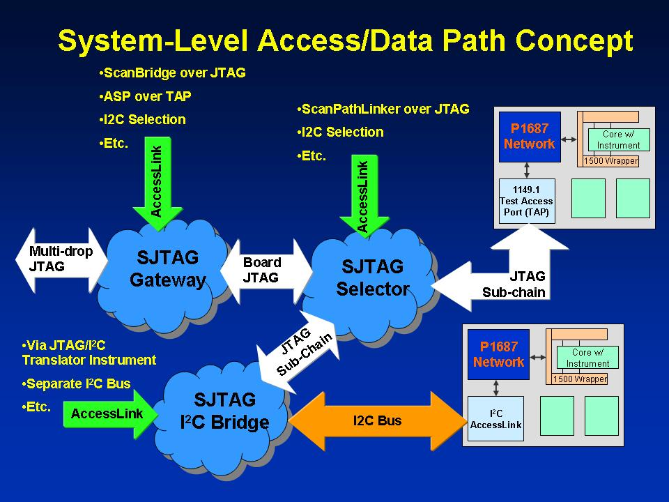 Figure 4 Access and Data Link Concepts
CONCLUSION
Testing at the board and system level is becoming more complicated as physical access to the board decreases and the speed of the logic increases. Embedded instrumentation is showing up on new designs to try to fill the gap created by this reality. These instruments are increasing the complexity of the board and system designs in order to provide access to these test features. To handle this complexity, a new way of thinking about the test infrastructure has to be used. The insights from the recent IEEE 1149.1 and IEEE P1687 standards have illustrated that the test data protocol may be decoupled from the access protocol if the data protocol follows a strict scan protocol based on the Capture-Shift-Update model established by the 1149.1 TAP State Machine. If that protocol can be maintained at the TDR level, then the access to that level should be able to be independently controlled to provide a means to apply that scan protocol at the TDR level through a variety of transport mechanisms. It is from that basis that this paper has attempted to describe a means for providing a decoupled connection method from the test data required to be transmitted over that connection. This paper has presented a series of examples where the data may be translated by higher level protocols that provide the behavior required at the next lower level, eventually scanning the required data through the TDR of a target instrument.
REFERENCES
- http://standards.ieee.org/findstds/standard/1149.1-2013.html
- http://grouper.ieee.org/groups/1687/
- http://www.latticesemi.com/~/media/Documents/ReferenceDesigns/1D/BSCAN2-MultipleScanPortLinker-Documentation.PDF
- http://www.firecron.com/webroot/index.php/pages/31
- http://www.ti.com/lit/ds/scbs686a/scbs686a.pdf
- http://grouper.ieee.org/groups/1149/7/
- http://thor.inemi.org/webdownload/projects/Test_TIG/BIST/BA-BIST_091113.pdf
Copyright © 2014, Bradford Van Treuren