
A Tale of Two Domains: Preprocessed Tests vs. Interactive Configuration
Green Paper
By Bradford G. Van Treuren, SJTAG Chair Emeritus
ABSTRACT
In this installment, I will be discussing the contrast between the need to support pre-generated tests, which are able to be replicated for factory testing, versus the need to support interactive configuration and control of an entity during Design Verification Test (DVT), Hardware Debugging (HWDB), and Software Debugging (SWDB). Both aspects are required to support the introduction of new designs. SJTAG needs to be able to support both these domains. The first usage domain deals with the traditional boundary-scan testing. A model of a circuit is created that defines the topology of the scan chain. An algorithm is applied to the model and a set of test vectors are created that can be applied to circuits matching that topology without needing to regenerate the vectors. The other domain concerns only a portion of the whole topology: a Test Data Register (TDR). This application modifies the configuration of one or more data registers (e.g., TDR) over a period of time to change the behavior of the device the registers reside in. The flow of the execution may not be the same for each execution of the application. This is because it is dependent on the state of the device, board, system, or a combination of some set of effectors monitored during the test operation.
PREPROCESSED TESTS
This usage domain is based on supporting the need of structural test techniques, which may be applied to the same circuit design without requiring the regeneration of the test. The same technique is then adapted to support programming of devices that adhered to the same circuit structure and algorithm. This pre-generated testing is only possible if the behavior of the circuit under test is going to be repeatable no matter how many times the test is applied. Therefore, the test may be represented as an ordered collection of test vectors without requiring the persistence of a circuit model to exist during the execution of the test. The key to making this possible is the vector set is defined to be applied to an entire circuit topology that does not change its configuration during the test. This execution model is what is implemented by most boundary-scan tools used today.
The traditional interconnect/continuity test is a good example of a test that may be automatically generated from the CAD data for a board and reapplied to all boards that match this CAD topology, without needing to be regenerated between each application. This test uses many different assumptions and testing techniques to handle the analysis of different types of net architectures. The simplest architecture is a pure Boundary-Scan architecture where all device pins support IEEE 1149.1 allowing for a full coverage of testing from one point to the other, with full visibility to the connection end points. Still other architectures may only provide a partial coverage because not all end points of the circuit are observable or drivable with 1149.1. However, a certain level of test may still be performed on these circuits to give shorts testing coverage. The vector patterns are pre-generated and the resulting responses are analyzed as a post process to determine the state of the circuit under test. So a circuit being tested may not behave the same as a circuit previously tested, depending on the fault conditions introduced to the circuit.
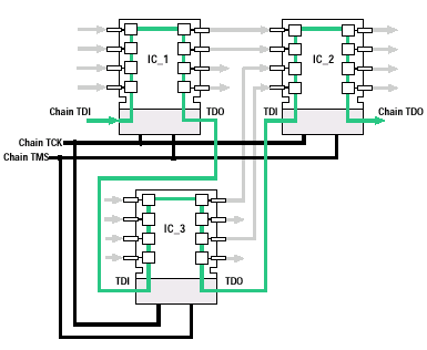 Figure 1 Example Board Topology
System level testing has expanded this capability by retargeting vector sets intermixed with board selection commands that change the topology connected to the tester. This opens the opportunity to target select chain segments dynamically. A tester tool is required to interject the chain configuration commands with the actual scan commands providing a good example of where there needs to be a configuration of an access link (aka, AccessLink in 1149.1-2013 and 1687 terminology) prior to being able to apply the data to the data link (aka, DataLink in 1149.1-2013 and 1687 terminology) of the selected scan sub-chain. Still, these tests are pre-generated for the specific topology of the target chain segment. But this concept paves the way to understand the retargeting as described by the new IEEE 1149.1-2013 and IEEE 1687-2014 standards. The configuration of the scan chain topology must be set up prior to being able to scan the data to the appropriate scan chain segment.
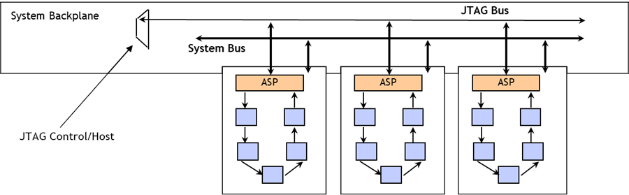 Figure 2 Example Multi-drop Topology
Industry is already making use of specialized “cluster” tests that target specific TDR subsets of a scan chain, without possibly realizing it. Test applications used for testing the memory interconnections and programming devices leverage the concept of targeting a specific subset of the entire chain topology without ever employing the use of IEEE 1149.1-2013 and IEEE 1687-2014. These applications apply a specific algorithm to a targeted TDR subset of a scan chain by applying an ordered set of vector patterns through that TDR to perform the intended operation. All these applications allow for a predefined vector set to be created that may be applied to any circuit matching this same topology. Thus, they are still considered preprocessed tests.
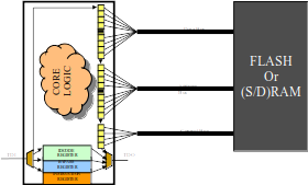 Figure 3 Cluster Topology
INTERACTIVE CONFIGURATION
In the interactive configuration domain, a chain segment is altered or monitored in real time to change the behavior of the system over time. This can be implemented with predefined scripts or through interactive tools from a Graphical User Interface (GUI). Traditionally, tools for this domain rely on a preconfigured topology and retarget the specific vector aimed for a targeted TDR as part of the overall global vector of the topology. This is done by padding the surrounding bits with safe values or values used to condition the circuit under test. Descriptions provided by IEEE 1149.1-2013 and IEEE 1687-2014 provide a standardized way to describe the topology surrounding a TDR within a device. But these standards do not provide a topological perspective at the board and system levels. Proprietary formats are generally provided by tool vendors to configure a particular access mechanism path allowing communications to a targeted TDR. The tools then provide the necessary padding bits surrounding the TDR in the given topology. More sophisticated tooling allows for the access to more than one TDR in a given scan or sequenced with topology altering commands that reconfigure a topology to a different TDR orientation. This provides the coordination of multiple instruments to operate as a single collective.
As mentioned, IEEE 1149.1-2013 and IEEE 1687-2014 both only address the structure and access to instrumentation inside a single device and do not address the access at the board and system level. Their existence is to provide a means for the instrument designer to specify the behavior of their instrument so it may be used during device testing or board and system level testing when wrapped with additional tooling that manages the access and data transmission outside of the device. There are some tool vendors who are providing proprietary tooling surrounding these new standards to allow for the control and management of instruments from a board or system level access connection. But these tools are still in their infancy and limit the complexity of the instrument cluster allowed to be controlled. Still, like every other advancement in this field, they are validating the concept for managing such embedded instrumentation.
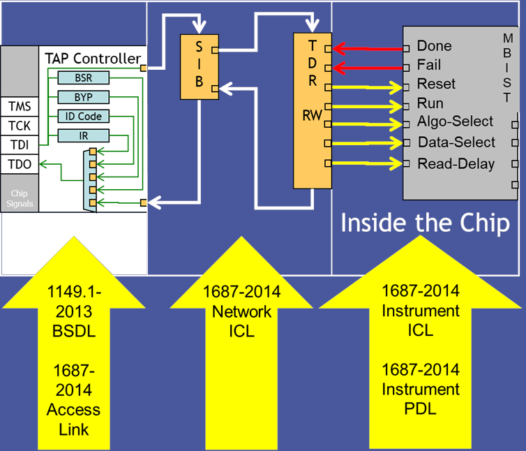 Figure 4 Example IEEE 1687-2014/IEEE 1149.1-2013 Topology
Industry experts have shared numerous examples describing how their application requires the ability to start a Built-In Self Test (BIST) operation while monitoring thermal sensors and voltage monitors to ensure the BIST operation is not misbehaving. If the application detects a temperature or voltage that is out of margins, the BIST test is immediately halted and the device/board is configured back to a safe state. It is this dynamic monitoring aspect that differentiates this type of test from the pre-generated tests described earlier. The flow of exiting the test is able to be altered at any point in time due to parameters that are outside of expected values. These parameters are in most cases a range of results and not a specific value being tested for. Therefore, the vector representation does not lend itself to static and fixed values presented by formats such as the Serial Vector Format (SVF). The Standard Test and Programming Language (STAPL) has some ability to handle dynamic and variable changes of a value, but the code becomes so complex and large to handle all the individual discrete cases of values that it may be impossible to store in the tester’s memory. What is needed is the ability to test for a target range of values using inequalities instead of explicit value tests. This is what PDL is trying to provide with IEEE 1149.1-2013 and IEEE 1687-2014 and is one of the benefits of describing the behavior in PDL over something like STAPL. These are high level programming constructs found in most high level programming languages. PDL leverages the programming constructs of the Tool Command Language (Tcl) to provide such features.
As designs of systems, boards, and devices get smaller, there still is a need to monitor the integrity of signals, values of temperatures, values of voltage rails, and many other conditions on the unit being tested. To provide access and eliminate the introduction of external noise by external test probes, many designs are now incorporating embedded instrumentation that is used by various aspects of a product test life cycle. During DVT, an engineer may need to monitor the voltage of a number of power rails within a design while the design is operating to ensure there are no power drops or spikes during operation. A design may be required to be housed in a cabinet that provides sufficient heat abatement to be able to operate within desired parameters. This prevents access to the circuit for monitoring and requires the use of embedded instrumentation. Much of this instrumentation is available as I2C based packages that easily fit on a circuit board to provide such monitoring. Many designs manage these I2C packages from an FPGA interface or from a Microcontroller interface to provide a view of the signals values measured by these instruments. This requires some level of firmware to be available in the product during DVT to provide the logic in the FPGAs and the software to translate these values back to a user interface where they can be processed by some controlling test process. Typically, this requires a special test load of the software that has to coordinate the sampling of the monitor instruments with the function being performed by the circuit. In many cases, this does not provide a good representation of the real operation of the circuit and software and introduces overhead that could hide timing problems within a design. Ideally, direct access to these instruments is desired to where a tester could non-intrusively monitor the values while the circuit under test is performing its role without requiring special application software.
This insight reveals additional issues SJTAG needs to consider. The issue of controlling an instrument interface indirectly through another embedded instrument acting as a bridge to the intended instrument is a real application that is not currently covered by the descriptions provided from IEEE 1149.1-2013 and IEEE 1687, as these standards assume the access is directly to an instrument register and not indirectly through a secondary interface. It also identifies a case where an instrument may reside behind some synthetic instrument that acts as an intelligent instrument managing the roles of its subordinate instruments.
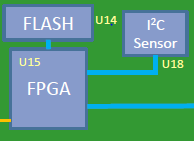 Figure 5 FPGA Controlled Sensor Monitoring
The Debug Access Port (DAP) or Board Debug Mode (BDM), found in most processors today, incorporates embedded instrumentation within the processor package to be able to control and interrogate the registers and memory space of a processor from an instrumentation interface. Many of the newer processors, especially the ARM Core technology, provide this access through the JTAG interface of the device. During a debug session, a software engineer is able to download software into the target, set break points, execute the code, halt the processor, and interrogate the values of registers and memory locations accessible by the processor. All these features are available through an interactive interface allowing the developer to single step through a program to observe how it behaves and how the circuit reacts to their code. This is accomplished via an interactive debug tool providing commands for the developer to use to invoke the correct feature of the interface. This same DAP and BDM is also able to be used by a special set of testing tools known as Processor Emulation Test (PET) or Processor Controlled Test (PCT) where a test engineer may use a scripting language interface to execute and process these interactive commands to perform functional and structural tests on a target circuit without requiring software to reside on the target. These may be interactive scripts or canned libraries of tests able to be applied to any circuit containing a select topology by just providing the base address of the target circuit subset. In that way, the test may be reused, as is, for multiple applications to the same circuit design as well as similar designs incorporating the same circuit elements.
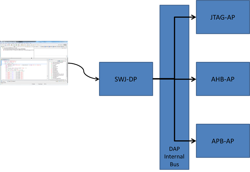 Figure 6 DAP Interface
OBSERVATIONS
When one steps back and looks at the preprocessed test domain, it should be obvious that the defined topology of the scan chain really consists of an ordered set of TDRs acting as a single entity where the pre-generated vectors are applied against. This configuration of selected TDRs remains constant throughout the entire execution of the test. In most tests, these TDRs are the Boundary-Scan Register (BSR) of a device, as defined by IEEE 1149.1. As patterns are applied, the behavior of the device’s pins change as they are dependent on the pattern set. But that is changing the behavior of how the device interacts with the board design. This is precisely what happens in the second domain too, but only to a different set of TDRs. So the common theme is that both domains operate on an ordered set of TDRs. However, the TDR set in the second domain may be altered at run-time to include or exclude additional TDRs.
The insight of the topology as an ordered set of TDRs is only part of the picture. The second insight is the execution model used for both domains. Traditional tools rely on scanning a vector through the entire topology in a single scan. This assumes the configuration of the topology remains constant or that each vector is composed of the aggregate of all the TDR values that have been retargeted into the correct order for a single scan operation. During application of the test, the length of the scan chain does not change and the order of the TDRs also remains constant. But we have demonstrated that this order can be changed when introducing the multi-drop topology to the test system. In that case, the whole topology changes for each board that is connected to the tester by the gateway device. Still, the test tool is able to scan out an entire vector representing the whole chain segment currently connected. In the case supporting 1149.1-2013 or 1687 instruments, the PDL is targeting a specific subset of the entire scan chain. If the tester tool is to scan out an entire vector for all TDRs assembled in a chain topology, the test tool must reassemble the ordering of the TDR data into a global vector using an operation known as retargeting by the standards. This retargeted vector is then applied to the entire scan chain by the tester tool. This retargeting can take a lot of time and infers multiple copies of the same data passed around in the data model of the target circuit. This can lead to inefficiencies as the circuit control requirements become more complex. There must be a better way. Michele Portolan and I introduced a new execution model, we developed in Bell Labs, that redefines the traditional execution model into a basic computer science problem of ordering operations based on a model using a simple binary search tree representation of the topology. It is efficient and small enough to be able to support embedded applications. Each segment scan then gets scheduled as to when it should be applied to the target. This provides for decomposing the complexity with delegation of the retargeting to the TDR representation in the model itself instead of by some retargeting process. The TDR model then submits a request to the scheduler to update its value and is allowed to do so at the appropriate time. The application of this vector segment requires a new application model for the TAP interface that allows for the gating of TCK between scan operations. This gating allows for the UUT to not realize there are multiple entities operating on the scan chain and that the scan operation is effectively the same as a retargeted global vector.
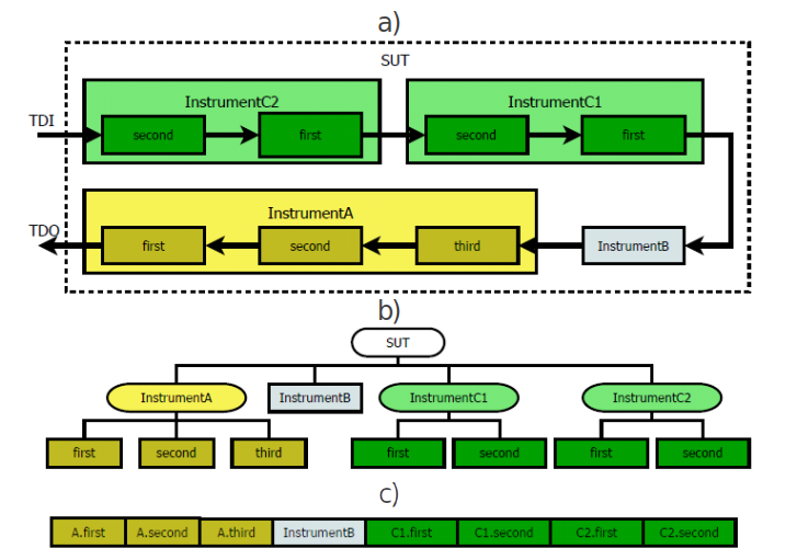 Figure 7 Test Instruction Set Architecture (TISA) Scheduler Circuit Model
CONCLUSIONS
Both of the domains discussed in this paper realize similar execution primitives and implement the same basic set of operations. It is how these primitive scan operations are used at the top level that separates the role of each domain. The preprocessed test domain could be mapped into the interactive configuration domain without much effort. This is because the interactive configuration domain is really a superset of the preprocessed test domain. The root difference between these two domains is not the scan primitives, but instead is the modeling of the topological structure of the scan chain segments used as part of the test generation and application. Each domain is using its own modeling techniques and makes different assumptions about the circuit model that differentiates itself from the other domain. Thus, if SJTAG is able to define a modeling architecture that is able to describe the requirements of both domains and the execution implementation that supports both a global scan as well as an aggregate scan of individual autonomous TDRs, SJTAG would be able to unify both domains into a single representation that is able to describe both the traditional testing applications as well as the newer and more advanced embedded instrumentation applications. This will probably require some sort of a Meta Language representation that defines the interactions at the board and system level in a more abstract relationship than one finds in the device level standards.
As this is a Green Paper, I hope you find this information intriguing and sparks an interest to discuss this subject further to provide assistance to the SJTAG study group to interject your own ideas and requirements for your test needs at the board and system levels. We can be reached through the web site: http://www.sjtag.org.
Additional References
- IEEE Std 1687-2014, http://standards.ieee.org/findstds/standard/1687-2014.html
- IEEE Std 1149.1-2013, http://standards.ieee.org/findstds/standard/1149.1-2013.html
- “CoreSight Components Technical Reference Manual”, http://infocenter.arm.com/help/topic/com.arm.doc.ddi0314h/DDI0314H_coresight_components_trm.pdf
- Portolan, M.; Van Treuren, B.; Goyal, S., “Executing IJTAG: Are Vectors Enough?,” Design & Test, IEEE , vol.30, no.5, pp.15,25, Oct. 2013 doi: 10.1109/MDAT.2013.2278541 URL: http://ieeexplore.ieee.org/stamp/stamp.jsp?tp=&arnumber=6584739&isnumber=6687242