
A Tale of Two Domains: Explicit vs. Implicit Selection
Green Paper
By Bradford G. Van Treuren, SJTAG Chair Emeritus
ABSTRACT
In this paper, I plan to present a comparison and contrast to the issues of chain selection as used by several well known use cases for board level testing. During the formation of the IEEE 1687 standard draft, there was much debate regarding whether the test engineer should be responsible for configuring the topology of the scan chain inside of a device or should the tooling be able to automatically configure the topology based on what actions were being applied to the hardware. On one side, engineers like to be able to have control over tools to give them a way to override assumptions a tool uses for cases where they do not match the desired behavior. Further, engineers have to deal with board and chip designs that do not always comply with a given standard. On the flip side, topologies are getting quite complex and it is difficult and time consuming for an engineer to map out and configure the appropriate topology for a given set of actions. This is especially true for actions requiring the selection of different instruments residing down separate hierarchical trees inside of a device. Power management inside devices today complicates this problem even further. If too many methods for selecting a topographical path through a device are used, it becomes a very difficult task for tools to be able to model the sequences that have to be performed in order to select or deselect a particular path. This is even more difficult as you move up in the hierarchy to the board and system levels.
For the discussion in this paper, I will present the hardware and modeling insights of each of the standards to give a general overview describing the key aspects of how the mechanism selects the different target registers and how a particular scan chain is able to be removed or ignored from the topology. I will also try to present the key aspects of how these mechanisms are modeled and how they are assumed to be controlled by the tooling. As this is a Green Paper, I will conclude with presenting the issues that I feel need to be addressed by the board and system test community and give insight to the decisions that the SJTAG Study Group has to face.
IEEE 1500 INSIGHTS
Hardware
This standard was the first attempt to standardize the way people accessed a collection of core registers together inside of a chip. The selection of the particular data register to be accessed is controlled by the value residing in the WIR (Wrapper Instruction Register) at the time. The WIR is selected to be wired between the WSI and WSO serial ports of the wrapper using a special selectWIR signal that is controlled by the system integrator designing the Test Access Mechanism (TAM). This may be controlled with the IEEE 1149.1 TAP Controller. There is a WBY (Wrapper BYPASS Register) required by a design to provide a mechanism to bypass a particular core while only adding one additional bit to the scan chain. I am excluding the discussion of the Wrapper Parallel Port (WPP) alternate access from this discussion as we are concerned with the scan chain topology features only for this discussion.
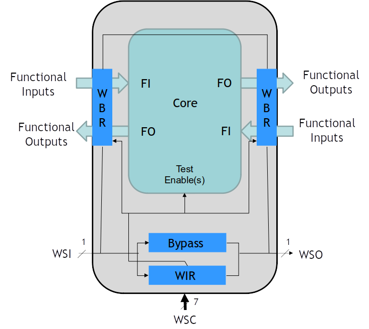 Figure 1 Mandatory Components of IEEE 1500 Wrapper
Modeling
The description of the IEEE 1500 topology and the various commands that may be applied to the wrapper are defined using the Core Test Language (CTL) as defined by the standard IEEE 1450.6. The description for this standard’s section 17.1.2.c states, “The intention is for the high-level information model provided by CTL to allow such pattern generation to be possible without need for access to the core’s or even the wrapper’s netlist definition.” This model is to be a high-level model describing only the key aspects required for access and operation.
Individual registers inside the wrapper are specified using the ScanStructures section. This defines the characteristics of the register and names the particular register as a named chain segment. For example:
ScanStructures bypass_mode_chains {
ScanChain bypassChain {
ScanIn WSI;
ScanOut WSO;
ScanLength 1;
ScanCells c0;
ScanMasterClock WRCK;
}
}
The core designer also defines a series of patterns, which provide values for various signals and registers in the wrapper design that are able to be applied by a set of macros defined as separate pre-defined behavioral operations. These operations then apply the particular constant pattern values for each signal to the corresponding signals and perform the shift operation when instructed. For example this is the macro for initializing the BYPASS of the wrapper in the sample program of the standard:
MacroDefs {
setup_testmode{
W default_WFT;
V {WRSTN=0;}
V {wsp[0..5] = 110100;}
Shift {V {si_wir= \W instruction [0..3]; WRCK=P;}}
V {si_wir=X; WRCK=0; ShiftWR=0; UpdateWR=1;}
V {WRCK=P;}
V {WRCK = 0; SelectWIR=0; UpdateWR = 0;}
}
}
IEEE 1149.1-2013 INSIGHTS
Hardware
The 2013 edition of the IEEE 1149.1 standard has included some new features for describing access to Test Data Registers (TDRs) controlling embedded instrumentation inside of a device. It also provides definitions for how to describe the topology of the access to these TDRs as well as behavioral functions, which may be applied to the various TDRs specified. The mechanism for defining the topology of the access to a TDR is done through the package file. The designer defines a set of REGISTER_MNEMONICS and REGISTER_FIELDS for the register. A REGISTER_ASSEMBLY attribute may be used to group a set of registers in an ordered collection defining a larger chain segment. The segments defined in a REGISTER_ASSEMBLY may be REGISTER_FIELDS or other REGISTER_ASSEMBLY attributes, thereby allowing for a hierarchical description of registers to be defined as well as allowing for reuse of the REGISTER_FIELD definitions for multiple register instances. There are four special REGISTER_FIELDs specified in the STD_1149_1_2013 standard BSDL package file. These are the SegSel, SegStart, SegMux, and the DomCtrl fields. These fields are used to control excludable segments from the hierarchical topology. They define a specific mechanism for the exclusion of individual scan chain segments. The standard also provides a means to define selectable segments that are selected based on the decoding of a special decoding segment. Any other mechanism is not supported by the standard. This is a key point to understand as it simplifies the ability for a tool to automatically manage the access to a particular chain segment. The REGISTER_ACCESS attribute is used to define how the specific REGISTER_ASSEMBLY is included as a TDR in the BSDL file for the device.
Modeling
The structure of the data model is defined by the various register package files and the associated attributes defining the hierarchy of the topology. The control of the TDRs is done using a new file type implementing the Procedural Description Language (PDL) instructions for a TDR described in a package file. This means the PDL instructions are completely TDR centric no matter where the TDR resides within the overall hierarchy. These instructions may be reused and applied to more than one instance of a particular TDR in the hierarchy as well - simplifying the development of instructions for the overall chip design. PDL defines a behavioral aspect of the TDR that was not previously possible for the core designer. The use of PDL Level-1 removes the restriction of patterns being a constant value and opens up the opportunity to alter the behavior of an instrument based on feedback observed.
Remember that the ability to exclude chain segments must be done using a specific hardware design solution. This design must follow this specific design architecture for the selection mechanism to work as described. If a design conforms to the hardware design requirements, tooling will be able to automatically manage the inclusion and exclusion of the scan chain segments. There are no mechanisms provided to describe any other chain management schemes. There is also no mechanism in the PDL to support external chain configurations short of writing your own Tcl commands using PDL Level-1. However, it is not clear how tools will react to user coded Tcl commands when they are applied. Since the PDL must be retargeted by the tool before being applied to the target UUT, the tool would most likely not be able to support hand crafted solutions for chain selection. The use of hand crafted solutions is not recommended.
IEEE 1687 INSIGHTS
Hardware
IEEE 1687 has some similarities in intent to the IEEE 1149.1-2013 standard, however, IEEE 1687 describes the connectivity and behavior of the instrument registers and not just to the TDR interfacing to the registers. As such, it has the ability to describe more conditions and behaviors of the hardware to allow the tooling to automate the control process easier. IEEE 1687 uses a separate language to describe the structural topology of the connection to the instrument. This language is the Instrument Connectivity Language (ICL). The purpose of the ICL is to define the path from the TAP Controller down to the instrument register being manipulated as well as all the hierarchical selection mechanisms required to be enabled to access the instrument register. ICL allows for the specification of various methods of selecting a particular instrument register, but the standardized exclusion mechanism is the SIB (Segment Insertion Bit). With a SIB, a value is written to it to include a sub-chain or to bypass the sub-chain. As a standardized mechanism, tooling is able to automatically manage the inclusion and exclusion of scan chain segments from the overall scan path through the device to be able to optimize the length of the scan chain for each scan operation.
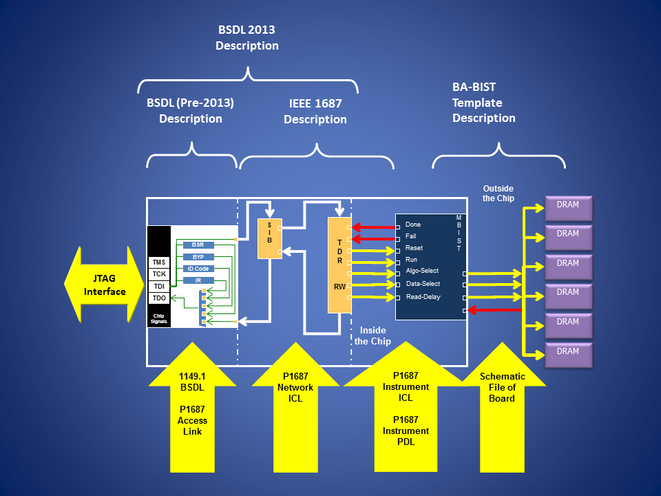 Figure 2 IEEE 1149.1-2013 and IEEE 1687 Instrumentation
Modeling
IEEE 1687 also includes a Procedural Description Language (PDL) to define the behavior of the various instrument registers, unlike the PDL of IEEE 1149.1 which targets the TDR that interfaces eventually to instrument registers. These procedures define the specific behavior of an operation by writing specific values to the appropriate instrument register in a specific order to cause the behavior to be performed by the instrument. Like in IEEE 1149.1-2013, there is no required naming convention for any of the procedures written for a user domain register. It is left up to the user to define the names of the procedures. The tooling is assumed to manage the selection of the correct scan topology to access a target register during the retargeting process. Thus, the tooling needs to support only the SIB design as the access selection mechanism for control of the chain hierarchy. Once an iApply statement is executed, the patterns defined by the iWrite, iScan, and iRead statements for an instrument register are retargeted to the global scan chain with the appropriate intermediate scans required to configure the scan chain topology enabling access to the register.
OPENOCD INSIGHTS
Hardware
OpenOCD is an open source emulation tool set for primarily the ARM processor family. The tooling provides various commands to control the emulation interface of the ARM, the ability to apply SVF files to the target hardware, and JTAG scan operations on scan segments. With the advent of multiple core processors and multi-chip packaging, processor vendors are developing new architectures that are challenging the way emulation tools are able to interface to the debug features. OpenOCD refers to these mechanisms as JTAG Route Controllers (JRC). One such device that contains a JRC is the Texas Instrument OMAP3 processor family. The OMAP contains an ARM core and a DSP core in a single package. TI uses a special hardware selector, called the ICEPick, to manage the selection of the processor for the emulator to connect to the selectable processor core. OpenOCD provides a special set of commands aimed at controlling the JTAG topology. The jtag tapenable dotted.name triggers an event to execute an event handler defined with a system script to perform the sequence of commands required to condition the JRC to make the selection to that specific scan chain segment specified as dotted.name. The ICEPick is designed to be controlled using the standard JTAG interface of the device with specific values set to special selection registers within the device. Only one processor core is able to be selected at a time. The other processor scan chain is parked and not included in the chain topology. The design is similar to a scan path linker device, used at the board level, but only allows one secondary port to be connected at a time. OpenOCD also supports a jtag tapdisable dotted.name command to exclude a path. This command is also serviced by a command event handler for the given TAP.
 Figure 3 Texas Instruments ICEPick Router
Modeling
When OpenOCD initializes, it expects the user to have written a configuration file (in Tcl) defining the devices in the scan chain of the target board as well as any special requirements for the scan chain (e.g., TCK frequency, reset behaviors). This is accomplished by including various Tcl scripts in the appropriate order as to define the dependencies required by the next imported script file. The order is important as it is helping to build up the topology of the scan chain.
OpenOCD assumes the user is in total control of the topology and requires the user to perform the necessary connection operations as part of their script creation. This is typically required to be performed once during an emulation session. The problem with this model is the chain topology could change if you need to talk to more than one processor core at a time. So the assumption that only a single sub-chain would need to be active from a JRC is not representing the real case of chain selection at the System, Board, Device, or even Instrument levels. The assumption is far too restrictive.
The key insights from OpenOCD is they have been able to abstract out the calling of the JRC to a single common high-level behavioral command that calls a user defined event handler to perform the specialized behavior of selecting the target sub-chain. The sequences of operations to make that selection behavior happen are not applied to a single design architecture, but instead are defined by the user or tool provider for the particular instructions required for their JRC (dynamic modeling of the behavior). This provides a reconfigurable mechanism with a standardized implementation for the user and tools.
OBSERVATIONS AND CONCLUSIONS
Given this paper is a Green Paper, whose purpose is to foster dialog on this subject, I am not going to provide a biased conclusion about what method makes more sense. The truth is that each of these methods for chain management and control have their unique benefits and consequences. Each is formed out of the needs from a niche problem domain they are trying to resolve. They are beneficial for us to study for the board and system domain control to make us think and realize what aspects are important for each of our needs.
We have observed how IEEE 1500 requires explicit selection of TDRs by the system integrator using the WIR as the decoder to a single TDR path. IEEE 1149.1-2013 and IEEE 1687 provided a way to automate the selection further by limiting the access mechanism type to a specific set of selection architectures; each of which is able to be selected automatically by the tooling. OpenOCD required the user to specify the specific scan chain to select for the remaining operations by using a single high level selection command. This command delegates the behavior to a handler written by the chip designer to perform the necessary JTAG operations, which ultimately selects the desired path to the core of the target chip.
What does all this have to do with SJTAG? Everything. SJTAG is the glue technology that will allow access to these standards from a board and system level if done right. By looking at what is available to tooling today, we are able to understand the different aspects and use cases that the eventual SJTAG standard must support. Unfortunately, looking at these examples only leads to more questions that must be asked and answered.
As we learned in my previous Green Paper, ideally the AccessLink must be allowed to operate independently of the DataLink, however, there are many access mechanisms which require the use of values set by the DataLink transmission. This is especially true for the SIB and SegSel bits described in this paper. At the board level there is the ScanPath Linker devices and ScanBridge type devices that require configuration of JTAG based registers in the DataLink path in order to perform the selection of the secondary scan paths. Other board-level selection mechanisms use a different interface, such as I2C or SPI, to configure the access of the DataLink. Still others, like the TI ASP, repurpose the DataLink with a different protocol to perform the selection. Is SJTAG able to support all these different selection methods or should it be restrictive and allow only a specific set of methods to select a DataLink like 1149.1 and 1687 do?
The OpenOCD JRC allows only a single sub path to be selected at a time whereas the ScanPathLinker allows for one or more path combinations of sub paths to be connected. Is there a way to describe both from an SJTAG perspective?
IEEE 1687 and IEEE 1149.1-2013 provide the means to allow the tooling to implicitly control and manage the access to the necessary data registers of the target instruments during the test application. This allows the tooling to select the most optimal path through the device, where optimal may be defined as the shortest data path, the least amount of power consumed, the path allowing for the shortest test time, etc. No user intervention or configuration is required short of defining the circuit structure (data path netlist). In contrast, when a traditional ATPG based test (e.g., Interconnect Test) is applied to a board by a board test engineer, the board level tooling requires the test developer to explicitly state the path through the board in order to identify what devices will be included in the test ATPG solution. This configuration will remain constant for the life of that test, once configured. Should SJTAG require the tooling to automatically manage the path selection or should it leave the management up to the user?
Does SJTAG need to define the selection process via behavioral functional interfaces as part of the standard if the user has to define their test configuration? Can this be resolved by the tooling implicitly? If so, then how does a tool support my own proprietary Selector design to allow me to use it with the tooling? Today’s procedure of asking the tool vendor to write a special model/code to support such devices does not provide for a very fast response for support. Nor does it provide a standardized method that supports portability of a design across multiple tools like a PC base boundary-scan tester or an In-Circuit Tester? It would be better to be able to have a standardized way to describe to the tool how to communicate with a Selector and have SJTAG define the protocol for accessing it. Isn’t the Selector just another specialized instrument that the other standards should be able to support?
There is a need to be able to define how to communicate to the AccessLink with a behavioral method call that perhaps uses multiple calls to select a state for a path (ACTIVE, IDLE, RESET) before a second call is issued to update their particular state. Or, perhaps the selection method is parameterized. If parameterized, then how do you deal with differences in the number of secondary ports of the selection mechanism?
As you can see, there are still many unanswered questions regarding the role of SJTAG. Support for the board and system level domains complicates the standard further based on what people have successfully implemented in ad hoc and proprietary ways. On the one hand, SJTAG could restrict the architecture to a set of specific mechanisms, like what IEEE 1149.1 and IEEE 1687 have done. Thus, it could simplify the automatic management of chain topology. On the other hand, SJTAG could envision a way to allow the user to express his or her own selection method and place the burden of chain management on the user. For ATPG, the user already needs to define to the tool the target devices that are to be included in the test. Does this require the manual definition of the chain topology to give the tool this insight as well as what precondition data values and instructions are to be used for each TDR?
We are left with a better understanding of the issues SJTAG faces in the area of chain management. However, we have only raised more questions that need to be answered before a standard may be completed. As mentioned earlier, no conclusion has been drawn out of this discussion other than each method becomes a polarizing justification to why one user prefers one method over another. The SJTAG Study Group encourages you to provide feedback as to what your needs for chain management are and what you are expecting the SJTAG standard to provide to meet those needs. Please study these issues and draw your own conclusions. We hope you will further express your conclusions back to the Study Group as your feedback and support. We can be reached through the web site: http://www.sjtag.org.
Additional References
- IEEE Std 1500
- IEEE Std 1687
- IEEE Std 1149.1-2013
- “Overview of the IEEE P1500 Standard”, Proceedings of the International Test Conference 2003, Paper 38.1.
- “Design Automation for IEEE P1687”, Proceedings of DATE 2011.
- “OpenOCD User’s Guide”, http://openocd.sourceforge.net/doc/html/
- “Tools for Debugging JTAG and Power Issues on DaVinci and OMAP devices”, http://www.ti.com/lit/ml/sprp603/sprp603.pdf?keyMatch=sprp603&tisearch=Search-EN
Copyright © 2014, Bradford Van Treuren